
Co-simulation based V&V
Meta-Information
Origin: Nadja Marko / ViF
Written: April 2019
Purpose: Construction and execution of a co-simulation scenario for verification of SuT.
Context/Pre-Conditions: Capabilities of models/simulation units have to match so that co-simulation is possible.
To consider: The development of simulation models requires domain knowledge so that the model represents real behaviour. Classical simulation models concern for example vehicle dynamics or other driving functions. For testing such vehicular ACPS, simulation models have to cover ADAS functionalities, sensor models and environment simulation where the latter is based on defined scenarios (see Scenario Generation Pattern). Further, code or real hardware can be integrated into the co-simulation and be tested early in the development process. Therefore, components that are part of the co-simulation are called simulation units and represent a simulation model, software or real hardware unit depending in which development phase the system is.
Structure
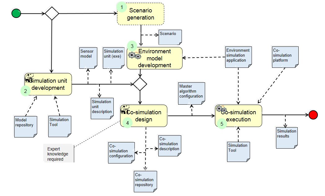
Participants and Important Artefacts
Model repository: contains the required, executable SuT models (simulation model(s)).
Simulation tool: Tool that simulates (provides solver) simulation model (e.g. Matlab/Simulink).
Scenario: A driving story representing real situations that will be simulated in an environment simulation application.
Sensor model: A simulation unit that represents sensor behavior.
Simulation units (slaves):: Simulation models or depending on the development stage real software or real hardware that should be integrated into the co-simulation. For testing ACPS sensor models, ADAS functions, and vehicle dynamic models are needed.
Simulation unit description: Description of simulation unit (accessible parameters, accepted input, output, supported step size, etc.). Description helps co-simulation engineer to couple individual simulation units.
Co-simulation description: The co-simulation description describes which simulation units are used for the co-simulation and which data is exchanged during the simulation. A tool can support the co-simulation expert in definition.
Co-simulation configuration: The co-simulation is configured concerning some parameters such as step size or capabilities of simulation units (e.g. set/unset logging).
Co-simulation Repository: A database in which co-simulation setups are stored.
Co-simulation Platform: A tool that implements a master algorithm and enables the configuration of a co-simulation scenario, coupling of simulation units, execution of the co-simulation scenario and viewing the results.
Environment simulation application: A tool for the creation, configuration, presentation and evaluation of virtual environments used in simulations for the development of ADAS.
Master algorithm configuration: A simulation master is an algorithm that controls the defined co-simulation scenario. This master is responsible for coordinating and coupling the simulation units. The master algorithm configuration includes for example the configuration of simulation step size or activation/deactivation of logging.
Simulation results: Data that is produced by executing the co-simulation and can include generated data of individual simulation units. With the simulation results the behavior of the SuT can be evaluated and checked against the requirements.
Domain experts: Experts (e.g. sensor expert or vehicle dynamics expert) that create simulation units (simulation models or real hardware).
Co-simulation (systems) engineer: System expert who has knowledge about requested system behavior. This person creates the co-simulation scenario based on existing simulation units and does the configuration.
Actions/Collaborations
(1) Scenario generation: see pattern “(Abstract) Scenarios Mining”.
(2) Simulation unit development: Simulation units can be developed from scratch or they use models from a model repository and make adaptions if needed.
(2.a) Domain experts develop simulation model/software/hardware that will be used for co-simulation. Simulation models include at least vehicle dynamics model and ADAS functionality. Further, sensor models have to be developed. These sensor models represent sensor behavior and interface of sensor model are object lists and/or sensor raw data.
(2.b) Domain experts describe developed simulation unit. They make a description of simulation unit so that co-simulation engineer can easily integrate simulation units based on this information.
(3) Environment model development: Based on the generated scenario, a virtual environment is developed with an environment simulation application. The development of this virtual environment includes the generation of road networks, traffic scenarios and weather and road properties. The creation of the environment model can be done automatically by a tool or manually by a domain expert.
(4) Co-simulation design: Co-simulation scenario is specified within this step. Output is a description of the co-simulation including configuration of the scenario and configuration of the simulation master (test platform, master algorithm) so that it can coordinate the co-simulation accordingly.
(4.a) Co-simulation engineer defines and couples (assigns input/output values) of simulation units that should be part of co-simulation.
(4.b) Co-simulation engineer defines environment model (scenario) to be used (coming from Scenario generation pattern).
(4.c) Co-simulation engineer defines sensor models to be used in the co-simulation and couples it with environment simulation and SuT.
(4.d) Co-simulation engineer configures co-simulation with appropriate properties (step size, capability flags, real-time simulation).
(5) Co-simulation execution: Execute co-simulation. Start co-simulation and exchange values between simulation units. This is done automatically by co-simulation platforms. If hardware is included, execution has to be in real-time. After co-simulation finishes, the simulation results are available and have to be stored.
Discussion
Benefits: Co-simulation based verification is flexible and modular. Simulation units (stored in a model repository) can be reused in other simulations. Simulation units can be substituted with software or hardware in case components have already been developed. Additionally, simulation models can be exchanged easily, e.g. change vehicle dynamics model because of new vehicle properties, without changing other models or tools, only input/output data have to match.
Comments:
– Mainly used in automotive applications, but concept can be used in other domains as well.
– Co-simulation methods are based on simple data types (int, float, …). Complex data types like object lists or images that come from environment simulation and sensor models need advanced co-simulation methods.
Application Examples
Co-simulation is used, for instance, in ENABLE-S3 use cases:
ENABLE-S3 UC1 “Highway Pilot”
ENABLE-S3 UC6 “Valet Parking”
ENABLE-S3 UC10 “Shore-based e-Navigation”
.
Relations to other Patterns
| Pattern Name | Relation* |
| Abstract Scenarios Mining | That pattern can be used to get scenario to be simulated |
| Formalized Verification and Analysis | Different approach, but uses also formal models |
| KPI Model-based validation | KPIs can be used to guide co-simulation |
* “this pattern” denotes the pattern described here, “that pattern” denotes the related pattern