
Model-Based Safety Analysis using Fault Injection
Meta-Information
Origin: Sven Sieverding, Omar Kacimi, Eckard Böde, / all OFFIS
Written: August 2014
Purpose: Given the increasing complexity of safety-critical systems, it is more and more difficult to perform safety assessment required by standards. The following pattern presents how to perform a so called Model-Based Safety Analysis (MBSA). Its results can be used for classical safety assessment techniques such as Fault Tree Analysis (FTA) and Failure Modes and Effect Analysis (FMEA).
The MBSA has two main prerequisites. First, the use of formal semantics to express the analyzed malfunctions as well as safety requirements. This allows to perform fault injection in the nominal system model and extending it to include the behavior in case of fault occurrences. Additionally, formal safety requirements can be translated into failure observers. Second, the underlying verification technique that analyzes whether the failure of the safety requirement can be observed in the extended system model. A typical result of a traditional safety analysis, that can be generated by the MBSA, is the minimal cut-sets (MCS) for a given safety requirement. Cut-sets are sets of fault combinations that cause the safety requirement to fail. Specifically, if any fault is removed from a minimal cut-set, the remaining set is no longer a cut-set.
Context/Pre-Conditions: safety analysis, requirements formalization, system design.
To consider: Implementing this pattern requires the involvement of a safety engineer. Also, the execution of the MBSA might be fairly time and resources consuming.
Structure
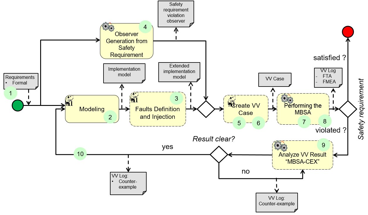
To keep diagram readable, not all inputs (artefacts) are shown here. They are displayed in the detailed diagrams below.
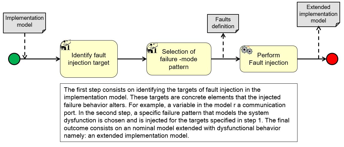
(3) Faults Definition and Injection:
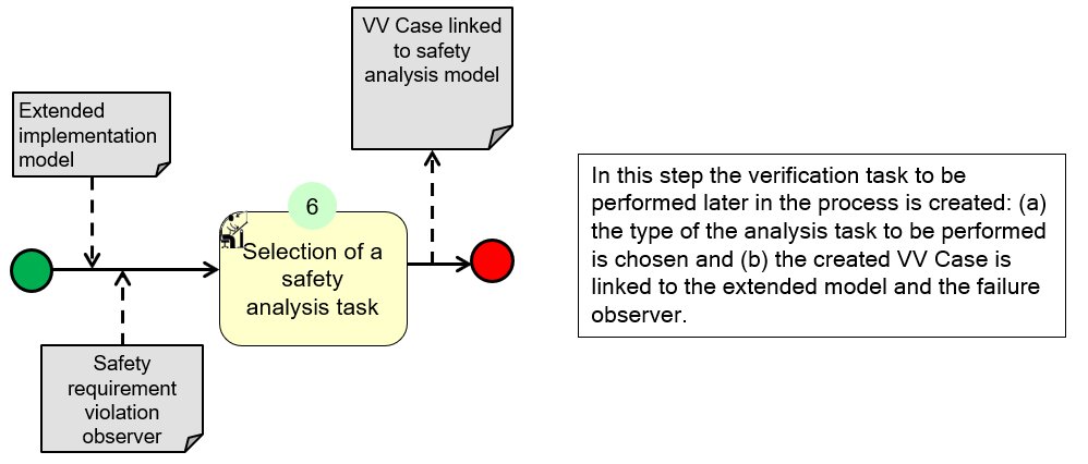
(5)(6) Create VV Case:
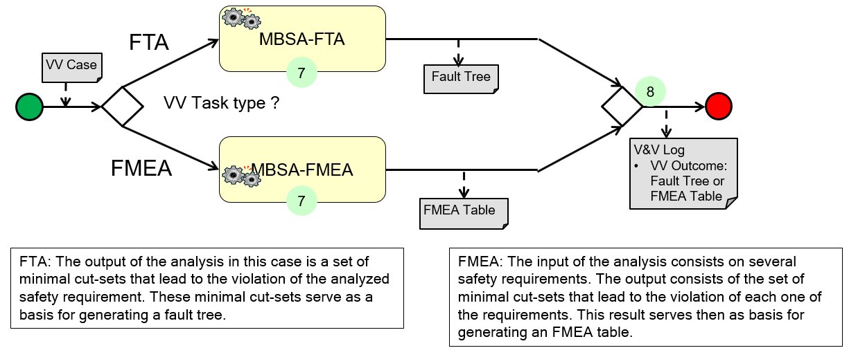
(7)(8) Performing the MBSA:
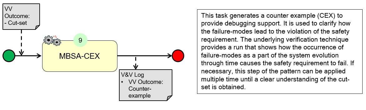
(9) Analyze VV Results “MBSA-CEX”:
Participants and Important Artefacts
Tools
Safety Analysis Tools:
– Fault injection tool
– Failure observer generation tool
– Failure-mode specification tool
– The model-based safety analysis
System and requirements design tools:
– Implementation model design tool
– Requirements formalization tool
Data
– Safety Requirements
– Implementation Model
– Faults (Modelling of possible failure behaviour)
Experts
V&V Experts:
– Safety engineer
– Analysis and test execution expert
Development Experts:
– System engineer
– Requirement engineers
.
Actions / Collaborations
(See also further information in the detailed flow diagrams.)
(1) Formal requirements are created on the basis of natural-language requirements.
(2) The system implementation model is created based on the formal requirements. Even if the workflow could start alternatively with natural language requirements, emphasis is put on formalized requirements to avoid the semantic ambiguity of natural language.
(3) Extending the nominal system model with dysfunction behavior using fault injection techniques, resulting in an extended system model.
(4) A failure observer of the analyzed safety requirement(s) is generated. This observer automaton will be used later at the level of the analysis to monitor whether the system has reached a failure state.
(5) A safety analysis task is created and linked to the extended model and the failure observer.
(6) The type of the safety analysis task is chosen, which can be either FMEA or FTA.
(7) The model-based safety analysis is performed.
(8) Finally, either a fault tree or an FMEA table is generated depending on the type of the analysis chosen.
(9) The safety engineer assesses the results and the outcomes for safety requirements violation (caused by the injected failure-modes). He can run a counter example (CEX) analysis to obtain a trace that shows how the faults lead to the violation of the requirement.
(10) The system engineer will modify the design according to the analysis results by introducing additional safety mechanisms.
.
Discussion
Benefit: The pattern reduces the manual analysis effort needed by the safety engineer in the case of a system update.
Limitation: The analysis might be time and resources consuming.
Comment: MCS can be used to automatically derive artifacts such as fault trees and FMEA tables. In some cases, the information contained in the generated safety artifacts is not trivial i.e. it is not clear how the occurrence of the malfunctions lead to the violation of the requirement. Accordingly, techniques such as model-checking can be used to generate a counter example (CEX) corresponding to a simulation run that shows clearly how the faults lead to a situation where the safety requirement is violated.
.
Application Examples
MBAT Automotive Use Case 3 (Adaptive Brake Light, by Daimler) / Scenario 03 (Is a state in the model reachable?):
Participants / Artefacts:
Modelling, structural: Papyrus, EAST-ADL
Modelling, behavioral: Matlab SF/SL
Modelling, formal requirements: The pattern Editor(OFFIS)
Faults definition: The FailureMode Editor (OFFIS)
Analysis configuration: the VV Editor (OFFIS)
Faults injection, Observer generation, Analysis: the Model-Based Safety Analysis (OFFIS)
Comments:
The Model-based safety analysis is used in this scenario to assess whether a state where the safety requirement‘s violation occurs is reachable in the system model in case the injected faults are activated.
.
Relations to other Patterns
| Pattern Name | Relation* |
| Model and Refinement Checking | That pattern could be used for MBSA-CEX if model is too fine-grained |
| Requirements Formalization | That pattern could be used for task “Formalize requirements” |
| Target MBA&T by Static Code Analysis | (Similar scope) that pattern helps focusing MBA in general (not only MBSA) |
| Support Safety Analysis by Faults Simulation | That pattern calls upon this pattern |
* “this pattern” denotes the pattern described here, “that pattern” denotes the related pattern