
Target MBA&T to Suspect Areas Identified by Static Code Analysis
Meta-Information
Origin: Brian Nielsen / Aalborg University, modified by Wolfgang Herzner / AIT
Written: October 2014
Purpose: The purpose of this pattern is to facilitate MB A&T targeted to suspect code area, to either find defects in this particular area, or increase confidence in their absence. An SCA tool will produce a report with defects and warnings. Code areas (moduls, components, functions, statement, variables,) where the warning density is high (or severe), should be prioritised with additional A&T.
Context/Pre-Conditions: Two levels of abstraction are involved, the lower „code“ level, and the abstract model-level. In this pattern, suspect areas are identified in the lower „code“ level. To enable subsequent A&T using the model it must be possible to create a mapping between the suspected area and the corresponding model-elements. This mapping may be established in different ways, depending how the model and code is related:
– Automated or manual, using traceability information that was annotated to model/code during their construction.
– Auto generated code: If the code is generated from the model, it may be possible to automatically to create the reverse mapping exploiting knowledge about the code generator and model using e.g. dataflow analysis (e.g. Daimler impact analysis for Simulink).
– Inspection is done manually.
To consider: Automated creation of the mapping may be fairly involved to do precisely. The user still needs some knowledge about what to do at the model-level to define new A&T Cases
Structure
Participants and Important Artefacts
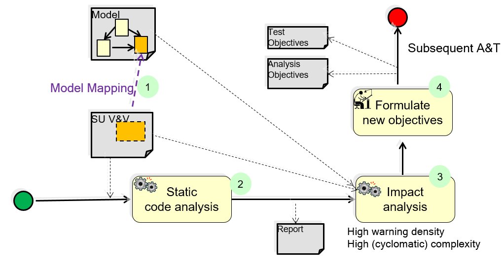
SU V&V: The target system being verified/validated: “System under verification and validation”.
Static Code Analyser: A tool that analyses (source) code by safe approximation techniques like abstract interpretation.
Impact Analysis: A tool (or manual procedure) that is capable of mapping code elementes to impacted model-elements.
V&V Engineer: A person responsible for creating A&T objectives or cases for the system under V&V.
.
Actions / Collaborations
(1) Model Mapping: links code level element (“defect area” e.g., function/statement) to Model-level element (for example, component or transition), by means of e.g.
– Traceability info?
– Auto generated code (e.g. Daimler impact analysis for Simulink)
– Manual inspection
(2) A static code analyzer (SCA) is configured and applied to the source code under investigation. This produces an analysis report containing a set of confirmed defects, and warnings.
(3) The impact analyser will input the model, source code, and the analysis report. First, it will identify suspected code areas (possibly assisted by the V&V Engineer), and next point out the corresponding model-elements, or the model-elements that may cause/influence the warnings.
(4) The V&V engineer will use this information and his understanding of the SU V&V and requirements to formulate additional A&T objectives or cases that target the possible defects in the suspected area. (Alternatively, if a large V&V suite exists, [s]he may extract those that are relevant to re-execute).
.
Discussion
Benefits:
– The V&V engineer will get higher confidence, or
– use less effort by prioritizing hotspots.
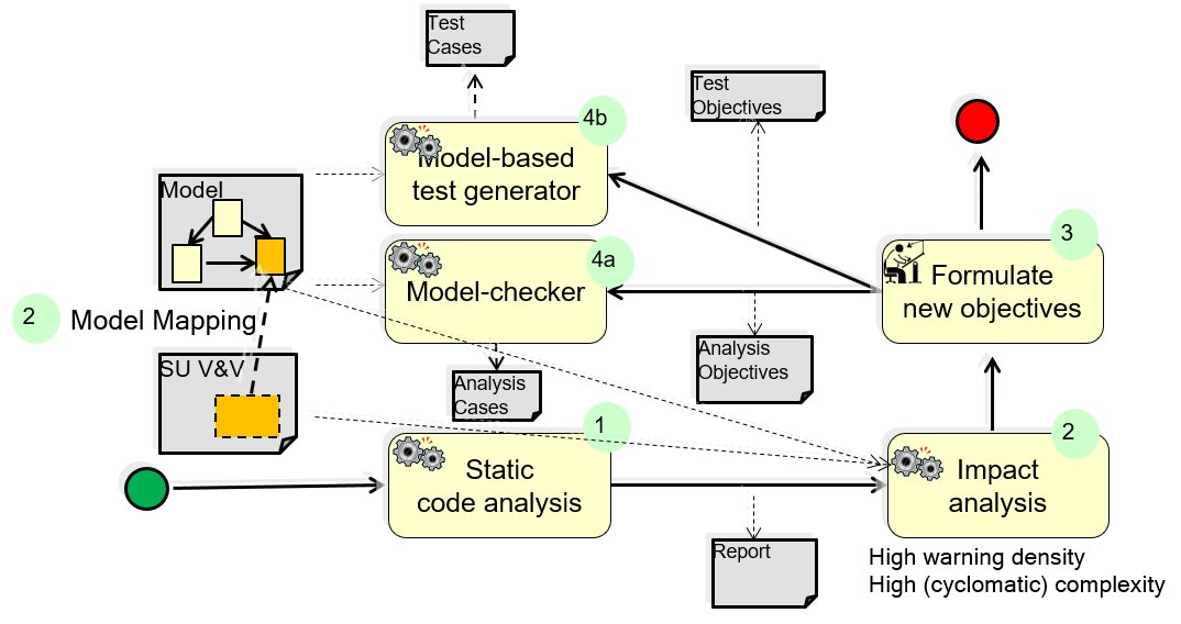
Comment:
– The main outcome of this pattern, in particular of action 4, are specific important analysis and/or test objectives that can be used to focus subsequent MBA and/or MBT activities. The following diagram illustrates this by an extended representation of the structure diagram.
Example for a possible use of the pattern: focus subsequent MBT and/or MBA
.
Application Example
MBAT Automotive Use case 2 – Daimler (Common Powertrain Controller) / Scenario 2 (Focus test and analysis activities):
Participants / Tools: Daimler, Astrée
Comment: Prioritises tests suited on impacted areas.
The block that was identified by Astrée is the input for an impact analysis. This impact analysis is a data flow analysis and identifies potentially affected outputs of a component. Since Simulink uses a dataflow oriented notation the dataflow analysis simply follows these explicit data flows. In case where the dataflow cannot be computed precisely a safe over approximation is used. Hence the identified component outputs are a super set of the truly affected outputs. This computation is done on all component levels up to the root level. Every time a component output at a certain level is identified the mapping data from requirements to the architecture is examined for potentially linked requirements. Thus the result of this analysis is a subset of potentially affected requirements and the associated parts of the system architecture.
.
Relations to other Patterns
| Pattern Name | Relation* |
| MBT | This pattern helps to focus MBT |
| Get Confidence in Generated Code | This pattern can use TCG from implementation model to check suspect areas |
| Support Safety Analysis by Fault Simulation | Similar patterns, as both generate test cases from analysis |
| Reduce Warnings from SCA | This pattern can help to avoid unneccesary work in that pattern |
| Target MBT to failing test case | Alternative ways to focus MBT |
* “this pattern” denotes the pattern described here, “that pattern” denotes the related pattern